
Abstract
The Test and Evaluation (T&E) ranges require two-way networked communications to provide gains in critical areas including: test efficiency, safety, cost savings and spectrum efficiency. The development of a network compatibility module which can accommodate networked telemetry standards while using existing commercial off-the-shelf (COTS) transmitter and receiver components has multiple benefits to the T&E test community. This component based approach to networked telemetry has the additional benefit of allowing new technology to be readily adopted for networking applications. This post reviews the progress made in the development of a standardized component based networking telemetry capability as well as other networked telemetry radio systems.
Introduction
The advantages of adding a control channel uplink to provide networking capability has been well established [1]. One focus has been to create a new type of radio to support uplink and downlink capability. Though this type of approach may have some merits in certain areas, it deviates from the proven evolution of componentized telemetry products. Products which provide two-way test article telemetry networking capability are already in use based on the latest generation of COTS receiver-transmitter components. This post was written to help identify potential paths for the reuse of the significant investment that the T&E ranges have in one-way telemetry links in providing a two-way networked capability. Telemetry communications products deployed on military test ranges has continued to push the envelope of closing very difficult RF links. Advancements in link stability and error reductions has been accomplished by introducing new and enhanced modes including adaptive equalization, space time coding, etc. The investment in this technology has been and will continue to be quite significant including vendor COTS products, range communications assets, and user knowledge base which results in successful flights every day.
In Section 1.0 of this post, a flexible component architecture is introduced which incorporates current transmitters and receiver products. Section 2.0 discusses the network controller and RF components which support this architecture. Section 3.0 covers key performance characteristics when using COTS radios in a networked application. Section 4.0 discusses channel access options when multiple telemetry transmitters are multiplexed on the same frequency for efficiency. Section 5.0 addresses compatibility to the Integrated Network Enhanced Telemetry (iNET) radio specifications and TmNS standards that apply to a TmNS compatible radio design. Lastly, the conclusion of this post summarizes findings and steps that can be taken to help achieve bi-directional telemetry capability as a readily available test range mission capability.
1.0 Bi-directional Telemetry Configurations
Some of the key components that can be configured to build a bi-directional telemetry system are shown in Figure 1. The system building blocks include COTS telemetry transmitters/receivers, RF filters/diplexers for Frequency Division Duplex (FDD) multiple frequency operation, an RF switch for Time Division Duplex (TDD) operation, antenna system components and a module to provide the serial to network conversion.

Figure 1 – Bi-directional Telemetry Components
Using these communications building blocks some of the possible network capability configurations that can be created are as shown in Figure 2. The bi-directional capability can be provided by a lower complexity approach with a FDD uplink channel on a separate frequency to the more complex single frequency sharing TDD network. The TDD capability provided can also range in complexity from a single up/down link, multiple uplinks, and at the extreme end many parallel missions sharing a single frequency capability.
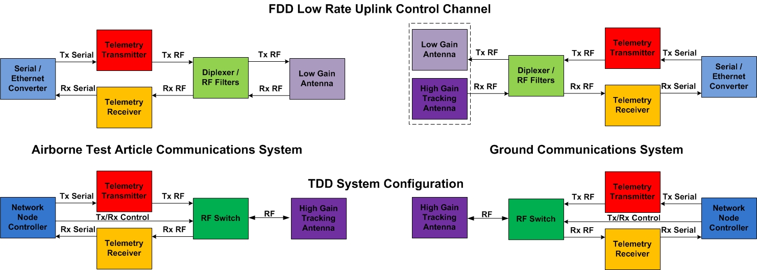
Figure 2 – Bi-directional Telemetry Configurations
Addition of Uplink Channel in Existing SST Telemetry System
A bidirectional capability can be introduced to the telemetry range system in various ways depending on the need of the range system and missions to be accomplished. For instance, an uplink can be added to an existing telemetry system which uses the existing Serial Streaming Telemetry (SST) transmission and infrastructure for the downlink as shown in Figure 3.
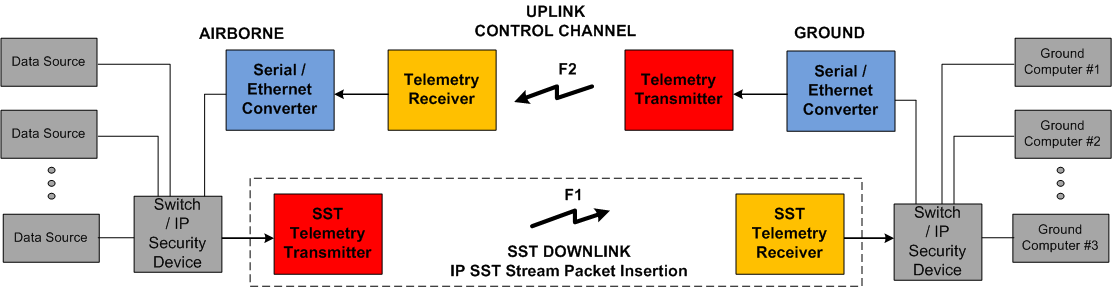
Figure 3 – Uplink added to Existing SST Telemetry System
The insertion of Ethernet frames containing IP packets on a downlink is an existing telemetry capability where data packets are inserted into the telemetry stream as defined in IRIG-106 Chapter 10 as an Ethernet packet type field [2][3].
Separate Frequency Uplink and Downlink (FDD)
A separate uplink frequency channel F1 and downlink frequency channel F2 representing two allocated frequencies can implement a telemetry bi-directional network link [4]. This may support an operation where the mission can support a telemetry link which is fully networked containing independent uplink and downlink IP data streams. One advantage to the FDD approach is the complexity of implementation and maintenance over a time shared TDD link is reduced. Also, each direction of the link can be more easily optimized for the type of link supported. An example of separate uplink/downlink optimization is selection of channel parameters on the uplink (e.g. data rate, coding, modulation) which can support the use of lower gain antenna attached to a high gain tracking antenna. One application of a bi-directional FDD system that has been deployed is the selection and control of video streams on a test article using a control channel on the uplink as shown in Figure 4.
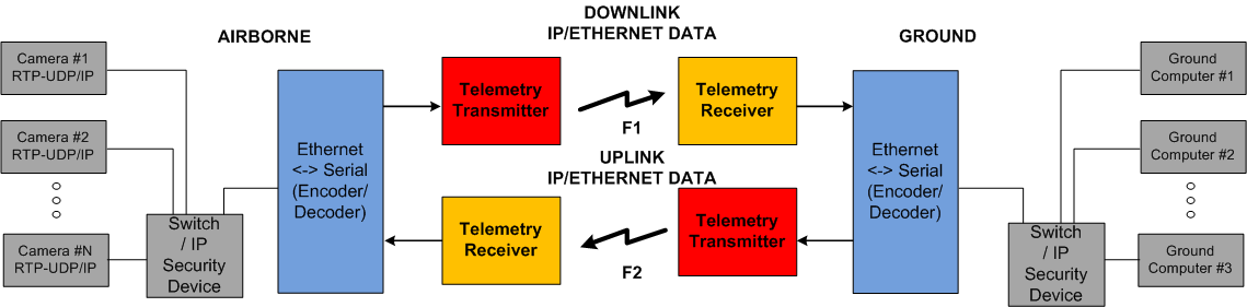
Figure 4 – Frequency Division Duplex (FDD) IP/Ethernet Based Telemetry System
Shared Frequency (TDD)
In a TDD telemetry system the higher complexity and efficiency of the link operation is traded for sharing of a single frequency. A time division channel access configuration is shown in Figure 5. The sharing of the allocated frequency F1 could be performed with a single ground to airborne link, multiple ground stations for added reliability/range, or in the more extreme case multiple missions operating in parallel. The allocation of time slots for transmission can be pre-configured or with link management control assigned dynamically during operation.
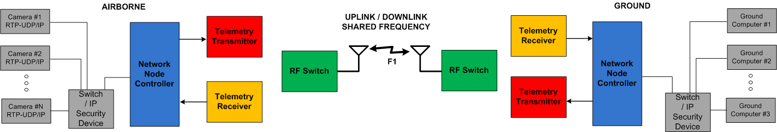
Figure 5 – Time Division Duplex (FDD) IP/Ethernet Based Telemetry System
2.0 Bi-Directional Telemetry Support Components
Serial / Ethernet Converter
The Serial / Ethernet translator provides Ethernet packet reception and conversion to serial data/clock outputs as shown in Figure 6. In addition to the format conversion, rate adaption is needed on the Ethernet Rx – RF Transmit conversion side when a higher rate Ethernet interface burst packets in at a higher rate than the RF transmit rate. The network function of this device is to simply reproduce the packets received when combined with a receiver and serial to Ethernet converter on the remote end.
Network Node Controller
The network node controller assumes the function of converting between Serial data and Ethernet streams and adds data and control plane functionality as shown in Figure 6. This node would typically be implemented with a General Purpose Processor (GPP) with Field Programmable Gate Array (FPGA) support and a lightweight Linux OS. Having control of both the data and radio control planes, the Network Node Controller can implement FDD and TDD channel access capability when configured with the external RF components. A TmNS standard managed node radio interface function can also be implemented in the node controller when required.
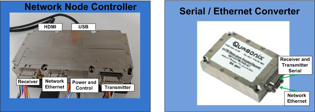
Figure 6 – Telemetry Node Controller and Serial/Ethernet Converter
RF Filters
Depending on the FDD operation being employed, some combination of filtering and or mixing of the RF transmit and receive signals may be needed to achieve the needed RF isolation of the uplink and downlink signal. An example diplexer used for FDD operation is shown in Figure 7.
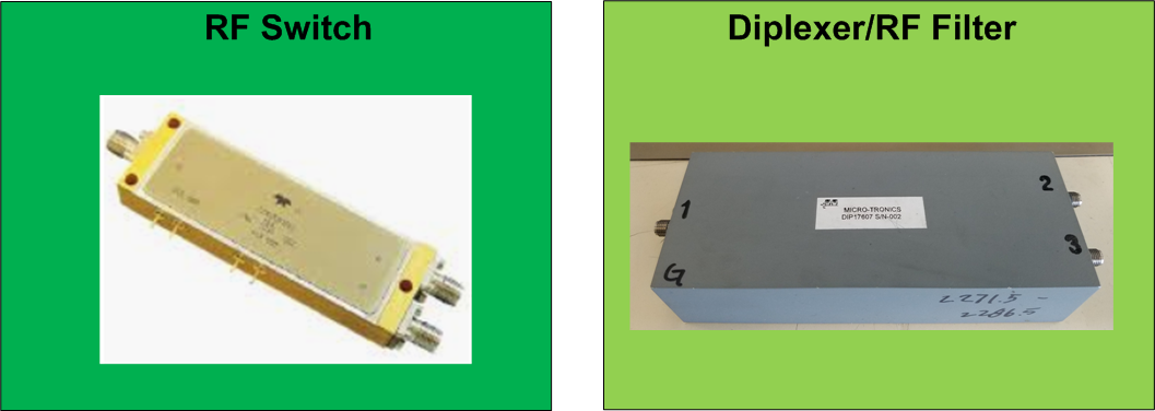
Figure 7 – RF Components
RF Switch
When operation on a single channel, the RF receive and transmit paths need to be switched under control of a Tx/Rx signal from the node controller. This component may be a separate component as shown in Figure 7 or integrated into the network node controller module.
Telemetry Transmitters / Receiver Components
Any of the IRIG standards based telemetry transmitters and receivers are suitable for FDD applications when combined with a the necessary RF components and network node controller / Serial-Ethernet converter. That being said, only compact receiver modules suitable for airborne applications would be of use. The COTS components that are of most value in supporting bi-directional FDD links are ones which can meet the transmit switching times and receiver synchronization times addressed in Chapter 3.
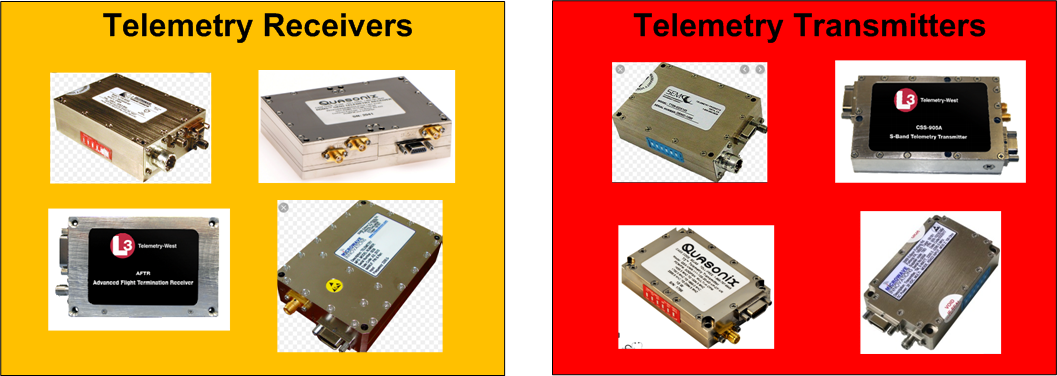
Figure 8 – Example Telemetry Receivers and Transmitter Components
Bi-Directional Telemetry Component Configuration
Combining telemetry transmitters, receivers and a RF Switch / Node controller module results in a configuration as shown in Figure 9. Products which provide two-way test article telemetry networking capability are currently in use deployed in FDD mode for airborne applications, with TDD systems to follow.
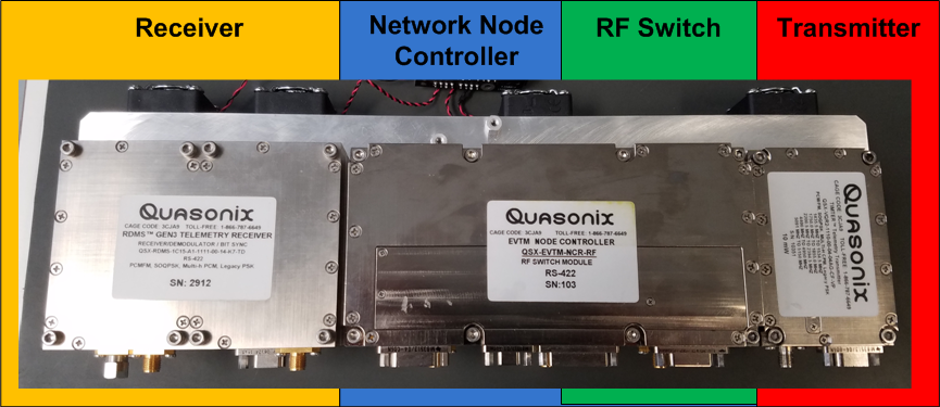
Figure 9 – Example Bi-directional Telemetry Configuration
3.0 TDD RF Switched Telemetry Performance
Transmit – Receive (T/R – R/T) Switching Times
Switching the Transmit Power output requires a time which for standard telemetry transmitters may not be optimized for dynamic operation. Since existing serial streaming telemetry systems are turned on or off based on start and end of missions, the internal control circuits and power filtering circuits may not be optimized for fast switching times. It is anticipated that some changes may be needed in transmitter designs to accommodate switching times for TDD operation combined with definition of a reasonable switching time target in the standards. The switching time supported by a transmitter needs to be accommodated in the TDD slot allocation as a programmable guard time along with propagation delay.
Receiver Synchronization
Telemetry receivers need to have fast re-synchronization of signals after loss due to outages. For switching involving a single transmit – receiver pair re-acquisition should be accommodated with minimal or no changes to the receiver design. When supporting configurations with multiple transmissions time multiplexed into a receiver the differences in frequency offsets need to be accommodated. Two areas of potential enhancement of the COTS receiver design are to use a unique identified at the beginning of each transmission to allow the receiver to store and recall the the synchronization settings from the previous transmission and/or the use of a correlation pattern at the beginning of each transmission period to provide rapid re-synchronization. Additional research and testing is still needed in this area.
TDD performance based on achievable component switching time
The TmNS standards are focused on a system to support a minimum of four simultaneous missions and a goal of 10 missions all sharing a single frequency. As a result of this designed in level of TDD sharing Transmit/Receive switching times on the order of 25 uS are specified.. Tight switching times and their significance is shown in Table 1.
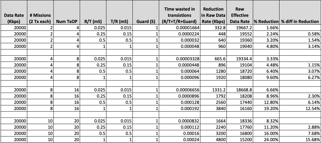
Table 1 – RF Switching Times and Link Efficiency
The calculations in the table show that only for large number of missions does relaxing the Receive/Transmit – Transmit/Receive times above the 25 uS level called out in the TmNS standards play a significant role in reducing the data throughput. Accommodating less extreme switching times would allow existing COTS transmitters and receivers to be used in a TmNS compliant role.
4.0 Bi-Directional Telemetry Shared Channel Access
TDD Master-Slave
In this channel access mode, the master test article transmits a transmit opportunity on a periodic basis to slave ground stations to transmit an uplink. This mode of operation does not require time sync on any mission application that has a single test article. If selected as the master the test article provides the time synchronization based on the transmission of a slave control message. A captured output of a lab test of a airborne master sending downstream data along with a transmit enable message to a ground radio is shown in Figure 10.
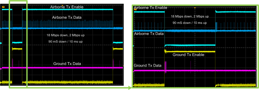
Figure 10 – Lab Test of TDD Master-Slave Mode
TDD Time Sync
In this mode, time synchronization is required at every node in the channel access network. In this case, transmission schedules can be set for multiple missions accommodating spatial reuse when missions transmissions do not conflict. Timing can be received from a network controller node which has a GPS receiver or interfaced to an external time source master.
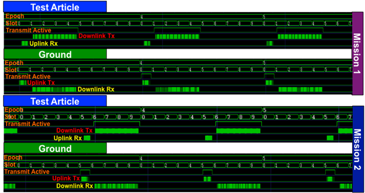
Figure 11 – Time Sync Mode With Test Article Master and Two Ground Slave Units
5.0 iNET/TmNS Functional Compatibility
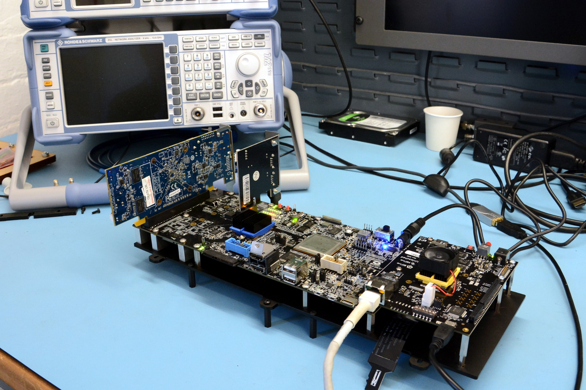
Any review of the TmNS standards specific to the development of an TmNS standards compatible managed node radio reveals a very feature rich set of capabilities [5][6][7]. Using the component approach as shown in Figure 12 the support for a COTS based TmNS managed node and link layer control can be contained in a separate COTS module which can be upgraded as needed independently of the transmitter / receiver modules. Functionality called out in the TmNS standards [5] can be supported as needed by the design of a Network node controller module with a modern embedded processor architecture running an efficient Linux Operating system.
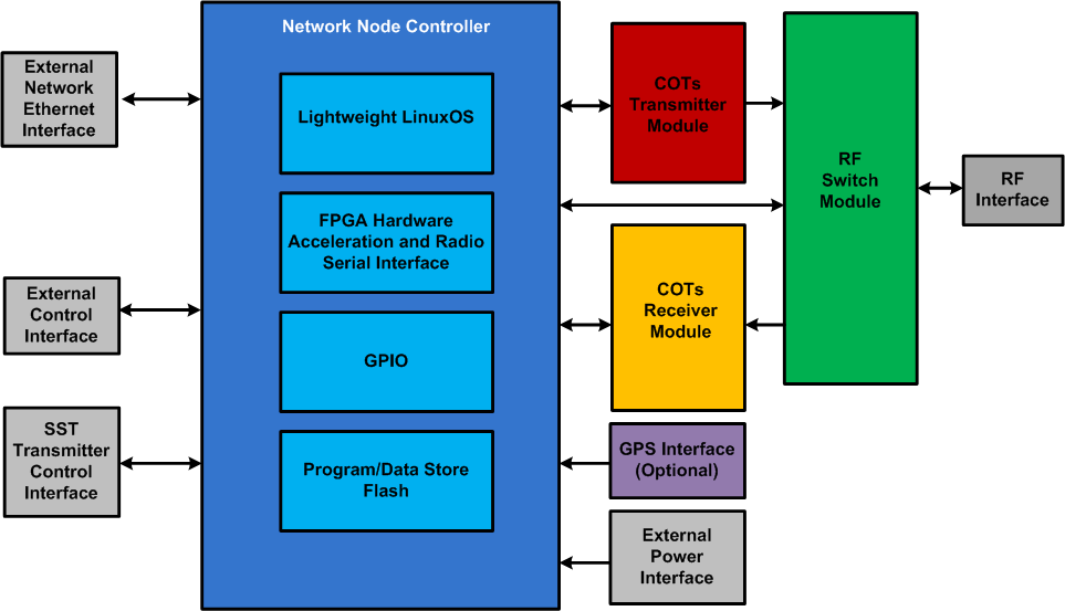
Figure 12 – Network Node Controller Component Approach to TmNS compatibility
Conclusions
The time to provide bi-direction link capability has come for the test range community, though the approach that is taken to provide radio hardware is key to the success. Only by promoting ways to leverage the significant investment in COTS hardware that exists today, improving the ability of radio vendors to support a networked radio capability and create an architecture which tracks current innovation, will bi-directional ‘networked’ capability take hold as a successful capability. The accommodation of a component building block approach provides significant promise based on capability currently in use today and potential for the broader use of this approach.
References
[1] Tom Young, “Integrated Network Enhanced Telemetry (iNET): Impact to the Telemetry Community for the ettc2018”, The European Test and Telemetry Conference – ettc2018
[2] Charles H. Jones, PhD, IRIG 106 Chapter 10 vs. iNET Packetization: Data Storage and Retrieval, Edwards Air Force Base, California
[3] IRIG-106 CHAPTER 10 DIGITAL RECORDING STANDARD (http://www.irig106.org/docs/106-07/chapter10.pdf)
[4] Matt Schultz, EVTM (Ethernet-Via-Telemetry): Get Ethernet Packetized Data Directly from Your Test Article
[5] TmNS Telemetry Standards, RCC Standard 106-17 Chapters 21-28, July 2017 (http://www.irig106.org/)
[6] Carl Reinwald, One Approach for Transitioning the iNET Standards into the IRIG 106 Telemetry Standards
[7] Todd A. Newton, M. Wayne Timme, Accelerating Standards Compliant TmNS Radio Implementations